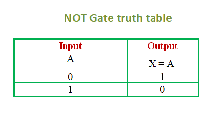
NOT here refers to the inverse or opposite state. When the input of a logic gate is ON, the output is OFF. And when the input is OFF, the output is ON.
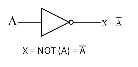
A gate that has only one input and one output is called a NOT gate. The output of the NOT gate is always opposite to the input.
Not gate expression
The value of output is always opposite to that of input A. According to Boolean algebra,
X = NOT (A)= Ā
If A = 0, then X = Ā = 1, and if A = 1, then X = Ā = 0.
Not logic gate symbol
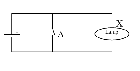
Not logic gate circuit diagram
Not gate using transistor
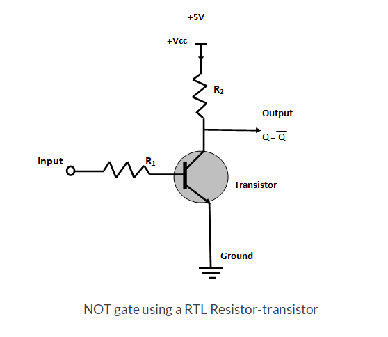
NOT gate (Inverters) can be implemented using a single PMOS transistor or a single NMOS transistor connecting with resistor. NOT gate (Inverters) can also be implemented with bipolar junction transistors (BJT) using a transistor-transistor logic (TTL) or a resistor–transistor logic (RTL).
NOT gate using a RTL Resistor-transistor switch is shown below. Here input is connected directly to the transistor base. When the transistor input will be “1” the current will flow to the transistor base. All the supply of voltage (+5V) will pass to the Ground through the resistor R. Since supply of voltage will drop across resistor R, voltage will be zero at output Q. In other words, the inverter output or NOT gate output will be “0” at Q.
Now if we give “0” in the transistor input, the base of the transistor will get zero “0” volt. There will be no current and the collector and emitter of the transistor will be OFF condition, Hence, there will be no path available to pass the current to the Ground. All the supply of voltage (+5V) will appear at the output. In other words, the inverter output or NOT gate output will be “1” at Q.
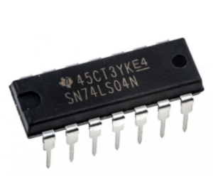
Not gate ic 7404
NOT Gate IC 7404 is made with six independent inverters which perform logical invert action. Each inverter makes output by the complement of its input logic state. When its input is 0 or low the output is 1 or high. This NOT Gate IC 7404 is a 14 pin DIP version of NOT Gate IC.
Related term :
3.Logic AND gate
